piping and instrument diagram ball mill
2021-04-11T00:04:36+00:00
Standard PID Symbols Legend Industry Standardized
Piping and Instrument Diagram Standard Symbols Detailed Documentation provides a standard set of shapes symbols for documenting PID and PFD, including standard shapes of instrument, valves, pump, heating exchanges, mixers, crushers, vessels, compressors, filters, motors and connecting shapes Piping and Instrumentation Diagram Documentation Criteria April 2008 functions included in the BPCS are cascade control, override control, and pump start/stop Also known as Basic Regulatory Controls (See also HLCS and SIS) bubble: Circular symbol used to denote and identify the purpose of an instrument or function ThePiping and Instrumentation Diagram Documentation Piping and Instrumentation Diagrams commonly referred to as PID’s are encountred nowadays throughout all process industries such as Oil Gas, chemical, pharmaceutical or food industries These engineering drawings are used worldwide in design, construction, commissioning, operation and maintenance of industrial plantsKnow Read Understand Piping Instrumentation
What is Piping and Instrumentation Diagram (PID) ?
During the design stage, the diagram also provides the basis for the development of system control schemes, allowing for further safety and operational investigations, such as a Hazard and operability study commonly pronounced as HAZOP For processing facilities, it is a pictorial representation of Key piping and instrument 6 GENERAL 61 Definition The Piping and Instrument Diagram (PID), based on the Process Flow Diagram (PFD), represents the technical realization of a process by means of graphical symbols for equipment and piping together with graphical symbols for process measurement and control functions(PDF) ENGINEERING STANDARD FOR PIPING isolation valve which isolates the instrument from the general piping, or the first two isolation valves when dual isolation valves are specified 114 This specification shall be applied to piping materials indicated on piping instrument diagram (P ID) and utility flow diagram (UFD) 115 Limits of the Piping SystemPIPING MATERIAL SPECIFICATION (PROJECT STANDARDS
I PIPING DIAGRAMS htproducts
6 All pumps are shown with isolation flanges or full port ball valves for isolation The alternative is standard flanges with full port ball valves and a separate flow check valve 7 Install a minimum of 12 diameters of straight pipe upstream of all circulators and check valves 8 ISA SYMBOLOGY The symbology for the identification of the measurement and control instrumentation on the flow and process diagrams and on the PID (Piping Instrument Diagram), commonly called PI (Piping Instrumentation), is generally PID Symbols (Complete List PDF) Projectmaterials The ball mill is an overflow type discharge mill, and is designed for a 45% ball charge Balls should be added on a regular basis as they are consumed in the mill The balls are added with a one ton ball bucket, lifted by an overhead crane, and discharged into the ball mill feed chuteGrinding and Classification Circuit 911 Metallurgist
Drawing BECHM100 Rev 24, 'PID Piping Symbols'
piping and instrument diagrams piping symbols pid instrument symbols pid instrument identifications p ball manual check mlØ6 mlØ7 mlØ8 mlØ9 mllØ mill m112 m113 m114 m115 m116 m117 m118 m119 m12Ø m121 m122 m123 m124 m125 m126 bechm127 bech m128 bech m129 bech6 GENERAL 61 Definition The Piping and Instrument Diagram (PID), based on the Process Flow Diagram (PFD), represents the technical realization of a process by means of graphical symbols for equipment and piping together with graphical symbols for process measurement and control functions(PDF) ENGINEERING STANDARD FOR PIPING Piping and Instrumentation Diagrams (PID) are schemes of pipelines, equipment, instrumentation, control systems, from a process system found in Oil Refinery, Chemical Plant, Paper Mill, Cement Plant, etc The symbols contained in P ID represent equipment such as actuators, sensors and controllers Process tools such as valves (valves), instruments,P ID common symbols, How to read a PID
A GRAPHICAL SYMBOLS FOR PIPING SYSTEMS AND PLANT
APPENDIX A GRAPHICAL SYMBOLS FOR PIPING SYSTEMS AND PLANT A 7 Solids Handling Size reduction Breaker gyratory Roll crusher Pulverizer : ball mill Mixing (basic symbol) Kneader Ribbon blender Double cone blender Filter (basic symbol, simple batch) Filter press (basic symbol) Rotary filter, film drier or flaker A 8 APPENDIX A GRAPHICAL SYMBOLS Final (detailed) piping and instrument diagram (PID) 2 General plot plan 3 Unit plot plan or equipment layout 4 Aboveground piping layout 5 Underground piping and foundation layout 6 Piping plans (erection drawings) 7 Isometric drawings 8 Line identification list 9 Material Takeoff list 10 Piping material specification 11 Piping Specification an overview ScienceDirect Topics PFD and PID are also known as PFS and PEFS PFD is a Process Flow Diagram PID is a Process or piping Instrument Diagram PFS means Process Flow Scheme and PEFS means Process Engineering Flow Scheme Here, I have tried to cover symbols that regularly used on the PID and PFDPID and PFD Drawing Symbols and Legend list (PFS
Piping Design Specification inspectionfor
Where this engineering specification is in contradiction with Piping and Instrument Diagram (PID) and Utility Flow Diagram (UFD), the OWNER’s approval for any decision is necessary 121 CODES AND STANDARDS PIPING DESIGN SPECIFICATION Design specification and inspection of piping shall be in accordance with the following Codes and Standards seamless piping less mill tolerance (eg, ASME B1611) The ratings of these components are addressed in the piping specifications provided in Appendix A If these components are used outside the limits established in the piping specification additional analysis and documentation must be provided 30223 Unlisted ComponentsASME B313 Process Piping Guide Los Alamos National Piping material for hydrogen service by William M Huitt (From a paper dated February 21, 2001 in response to a discussion on material for hydrogen piping) Fig 1 Nelson diagram – API 941 This diagram indicates the choice of steel warranted to avoid hydrogen attack as a function of operating temperature and partial pressure of hydrogen Piping material for hydrogen service W M Huitt Co
Explore the World of Piping
Dimensions and Weights (full) ASME B3610 Pipes (11 pages) NPS 1/8 NPS 80; Dimensions and Weights (full) ASME B3619 Pipes NPS 1/8 NPS 30; Dimensions and Weights of Pipes ASTM A53/A53MWhere this engineering specification is in contradiction with Piping and Instrument Diagram (PID) and Utility Flow Diagram (UFD), the OWNER’s approval for any decision is necessary 121 CODES AND STANDARDS PIPING DESIGN SPECIFICATION Design specification and inspection of piping shall be in accordance with the following Codes and StandardsPiping Design Specification inspectionfor APPENDIX A GRAPHICAL SYMBOLS FOR PIPING SYSTEMS AND PLANT A 7 Solids Handling Size reduction Breaker gyratory Roll crusher Pulverizer : ball mill Mixing (basic symbol) Kneader Ribbon blender Double cone blender Filter (basic symbol, simple batch) Filter press (basic symbol) Rotary filter, film drier or flaker A 8 APPENDIX A GRAPHICAL SYMBOLS A GRAPHICAL SYMBOLS FOR PIPING SYSTEMS AND PLANT
ENG470 Engineering Industrial Project Final Report
then conveyed to a ball mill for further size reduction The discharge from the mill is screened, then pumped into a gravity feed tank This tank feeds the gravity Process Flow Diagram (PFD) and Piping and Instrument Diagram (PID) stem from the Process Control Philosophy The following subheadings are relevant to the215 Ball 216 Plug 22 Valve Operators 221 Handwheels Levers 222 Gear Operators 223 Control 224 Pressure Safety/Relief 30 Bibliography 1 PIPE AND FITTINGS 11 A Brief History Piping has been discovered in civilizations dating back many thousands of yearsThe Basics of Piping – Process Piping Designer Piping material for hydrogen service by William M Huitt (From a paper dated February 21, 2001 in response to a discussion on material for hydrogen piping) Fig 1 Nelson diagram – API 941 This diagram indicates the choice of steel warranted to avoid hydrogen attack as a function of operating temperature and partial pressure of hydrogen Piping material for hydrogen service W M Huitt Co
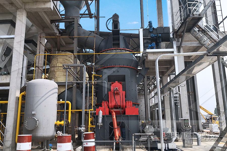
Chemical engineering Vector stencils library Piping
The vector stencils library "Chemical engineering" contains 24 symbols of chemical and process engineering equipment Use these shapes for drawing Process Flow Diagrams (PFD), Piping and Instrumentation Diagrams (PID), and Water Flow Diagrams in the ConceptDraw PRO software extended with the Chemical and Process Engineering solution from the Chemical and Process Crushers Centrifuges Motors Peripheral Piping and Connecting Shapes Instrument Valves Heat Exchanges Dryers General Vessels Standard PID Symbols Legend Industry Standardized PID Symbols Piping and Instrument Diagram Standard Symbols Detailed Prices / Quote Spain ball mill mining mineral is popular Prices / QuoteJaw Crusher Flow Sheet Symbol Soby Dimensions and Weights (full) ASME B3610 Pipes (11 pages) NPS 1/8 NPS 80; Dimensions and Weights (full) ASME B3619 Pipes NPS 1/8 NPS 30; Dimensions and Weights of Pipes ASTM A53/A53MExplore the World of Piping
The Piping Engineering World » The Piping
I hope this blog will be a good source of useful information for all your piping activities Thanks for visiting this blog Have a pleasant stay here!! Your suggestions and comments are highly welcomed you can write me a mail at Latest on “The Piping For its extensive practical experience, 911 Metallurgist has a clear understanding of what successful mineral processing engineering is and how to go about achieving itYour goal is the production of a material that is marketable and returns you and your investors sustainable revenuesMetallurgist Mineral Processing Engineer